.png)
.png)
Project 2 - Alarm & Light
Components


Build
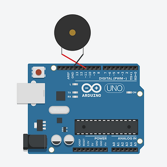
Step 1
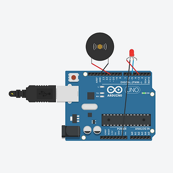
Connect the buzzer to the main board. This time, wires have been used to make the connections. The short buzzer lead (-) goes into GND. The long buzzer lead (+) goes into pin 11.
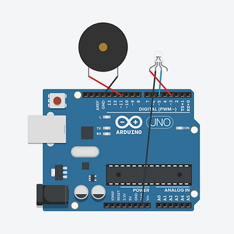
Step 2
Connect the RGB LED to the board. The longest leg of the LED is negative (-) and goes into GND. The leg by itself on one side of the long leg is the red light and goes into pin 3. The leg on the other side of long leg will be blue or green. Use trial and error, and then connect this leg to pin 5.
Step 3
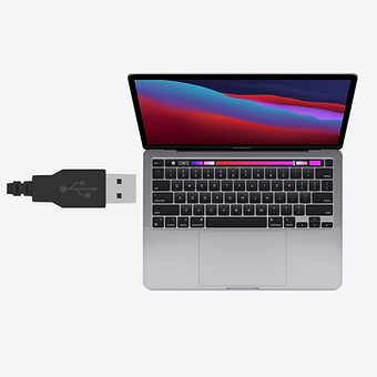
Plug the USB cable in to the main board.
Step 4
Connect the USB cable to the computer.
Step 5
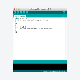
Find and open the Arduino application. Remember to select your board from the tools > port menu.
Code
Copy the code to the right and then open the Arduino application.
Delete all of the text that appears and then paste in this code that you have copied.
1.
2.
3.
4.
5.
6.
7.
8.
9.
10.
11.
12.
13.
14.
15.
16.
17.
18.
19.
20.
21.
22.
int buzzer = 11;
int redPin = 3;
int bluePin = 5;
int beepLength = 500;
void setup() {
pinMode(buzzer, OUTPUT);
pinMode(redPin, OUTPUT);
pinMode(bluePin, OUTPUT);
} // close setup
void loop() {
analogWrite(buzzer, 255);
analogWrite(redPin, 50);
analogWrite(bluePin, 0);
delay(beepLength);
analogWrite(buzzer, 0);
analogWrite(bluePin, 50);
analogWrite(redPin, 0);
delay(beepLength);
}
Click on the arrow shown in white to transfer the code to the Arduino Uno. You will need to give your sketch (program) a name. If the code is correct, the program will begin to run as soon as the code has transferred.

Explanation
The code first sets some words to represent numbers that are used in the program, and then labels the buzzer, red and blue lights as outputs.
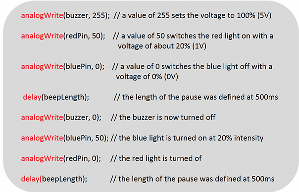
The analogWrite commands allows the intensity of the voltage delivered to a component to be varied. In this program, the intensity of the red and blue light are set to 50, with a maximum setting being 255.
Extension: Try adjusting the intensity of the lights in the program by changing the value to be between 0 and 255.
Also, can you change to code to include the green LED lead and have the lights alternate as red, blue and green?
Videos
Digital Build
Physical Build
Knowledge Base - int, analog write & board pins
The "int" function used at the start of this code is being used as a variable declaration which specifies that an "int" (integer - a whole number) will be stored using a specific name. In this code the integer 11 refers to the buzzer, 3 to the red light lead and 5 to the blue light lead. This allows words to be used in the code instead of numbers which helps keep track of what is being programmed.
The term digitalWrite used in the last project allows two settings: HIGH (on) or LOW (off). This means the voltage is either 5V (HIGH) or 0V (LOW). AnalogWrite allows the voltage to be set at any level by adjusting the numbers from 0 (0% or 0V) to 255 (100% or 5V). This allows the intensity of brightness of components like LEDs to be controlled more precisely.
The board has a range of pins including the ground pin (GND) which is the negative pin and means zero volts (0V). All other voltages in a circuit are measured relative to GND. There are 13 other numbered pins as well as six analog pins, labelled A0 to A5.