.png)
.png)
Project 3 - Xmas Light
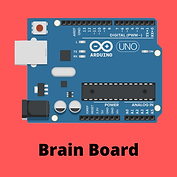
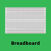
Components


Build

Step 1
Connect the LED to the breadboard with the longer lead (+) to the right and with each lead on a different row of the breadboard.

Step 2
Bend the leads of a 470Ω resistor into a "U" shape and add to the breadboard so that one resistor lead is in the same row as the "-" lead and the other resistor lead is in the negative sidebar of the breadboard.

Step 3
Connect a wire from the breadboard negative sidebar to one of the GND pins on the main board. Connect a second wire from the breadboard row with the "+" lead of the LED to pin 11. Plug the USB cable in to the main board.

Step 4
Connect the USB cable to the computer
Step 5
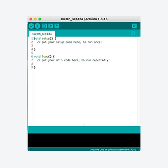
Find and open the Arduino application. Remember to select your board from the tools > port menu
Code
Copy the code to the right and then open the Arduino application.
Delete all of the text that appears and then paste in this code that you have copied.
1.
2.
3.
4.
5.
6.
7.
8.
9.
10.
11.
12.
13.
14.
15.
16.
17.
18.
19.
20.
21.
22.
int led = 11;
int brightness = 0;
int delayTime = 10;
void setup() {
pinMode(led, OUTPUT);
}
void loop() {
while(brightness < 255)
{
analogWrite(led, brightness);
delay(delayTime);
brightness = brightness + 1;
}
while(brightness > 0)
{
analogWrite(led, brightness);
delay(delayTime);
brightness = brightness - 1;
}
}
Click on the arrow shown in white to transfer the code to the Arduino Uno. You will need to give your sketch (program) a name. If the code is correct, the program will begin to run as soon as the code has transferred.

Explanation
There are two loops in this program that use the 'while' condition. The first part cycles the brightness of the LED from 0 (0V) up to 255 (5V). The second loop then cycles the LED from 255 (5V) back down to 0 (0V). The effect is the LED cycles through getting brighter and dimmer.

Extension: Try adjusting the length of the pauses in the program by changing the value for the delay.
Videos
Digital Build
Physical Build
Knowledge Base - resistors & "while" loop
Some of the components used in circuits can be damaged or may not work if the current or voltage passing through them is too high. To adjust the current or voltage delivered to a component, a resistor can be used. Resistors resist the flow of electricity and are measured in Ohms. Depending on the component, resistors of different strengths can be used. For example, in this project, if the maximum current was was passed through the LED, the LED could burn out, so a 470Ω resistor is used to reduce the current to a suitable level.
The while loop is used when a certain action is desired for as long as a declared condition is true.
In the first "while" loop, the declared condition for the loop to repeat is 'while' the brightness remains less than 255. For the second "while" loop, it is 'while' the brightness remains greater than zero. The first loop runs as the brightness is increased by 1 point every 10ms until the brightness reaches 255. At that time, the first 'while' loop finished and the second 'while' loop starts which decreases the brightness by 1 point every 10ms until the brightness reaches 0. This second loop is now complete and the program goes back to the start of the void loop () function and starts all over again.